1. What is Rock Conveyor Engineering?
Ans. It's the Android application for designing and calculating about belt conveyor.
2. What can it do?
Ans. It helps to design the necessary values for the design, such as calculating the load caused by the rollers. Calculate belt tension Calculate the weight used to counterbalance the belt etc.
3. Why use this?
Ans. Convenient to enter various values Fast calculation and standard procedure The answer is reliable and can actually be used.
4. Who is it suitable for?
Ans. Suitable for conveyor design engineers, plant engineers, material handling engineers Conveyor Equipment Sales Engineer Procurement officer Entrepreneur, contractor, design and installation of conveyor equipment As well as generally interested parties.
5. What else can it do?
Ans. Save and share answers immediately via email or online networks.
Example of use
After the survey, collected data on the job site Suppose that the information has been obtained as follows

Data know from the customer and measured from the worksite location (Figure 1)
Conveyor length = 48.25 m
Bulk material = Gypsum maximum lump size 3 inch
Correct bulk density = 78.5 lb/ft³
Design capacity = 260 TPH ( Tonnes per hour )
Idler type is 3 Roller idler set.
Drive pulley diameter = 480 mm with 10 mm rubber lagging ( Diamond groove )
Tail pulley diameter = 400 mm ( Bare pulley )
Wrap angle = 180 Degree.Primary cleaning device = 1 Ea.
V-Plow ( Full ) = 1 Ea.
Step 1.
Open the application ( Download from https://play.google.com/store/apps/details?id=com.appybuilder.anuwat_kongpan.ROCK_CONVEYOR_ENGINEERINGVSERT and install it on your device)
Step 2.
Go to the main page of the application.

Step 3. Select tail point ( location of the tail pulley ) by selecting from 2.1 at point "C" and select drive pulley point at point "D" and click "Confirm"

Step 4. Topic 2.3 will show on the main page application to get value from user input. For this example, the application needs "C-D Length" and "Delta 1" User input 48.25 m and 12 Degree into the textboxes ( Please see in the picture below ) and click "OK"

Step 5. Selec the bulk material from the material database by tab to "Tab to select material..." and select


Step 6. Recheck the data from the customer ( 78.5 lb/ft³) and change the specific weight from 60 to 78.5 and click "OK"

Step 7. Set the surcharge angle of the bulk material by click "Automatic Surcharge Value Setting "

Step 8. Input the maximum size of the material lump and click at the unit ( 3 Inch )

Step 9. Select the bulk material behavior on the belt ( 100 Percent Lump 30 Degree Surcharge )


Users can see "30 Inch" from guidance for belt width selection.
Step 10. Select Belt Width by equal or over the guidance value ( For this example use 36 Inch belt width)

Step 11. Input the required capacity 260 TPH

Step 12. Select the idler set type ( 3 Roller ) and input "Troughing set angle 1" then click "OK"

Troughing set angle 1 ( see below picture )

Step 13. Trial and Error Speed input process. First, Input any speed into the Velocity textbox and select unit ( For example input 1.5 m/s ) and see at the " Percent of designed capacity is ___ %"

We know the present speed will be affected by 37.98% to the capacity and try to reduce the speed to 1.0 m/s ( Input 1.0 and click "m/s" again )

After input 1.0 m/s, We know the capacity cross-section of the belt is 56.7 % ( Lower speed can reduce running cost, reduce gearbox price, etc.) For the good value of percent is more than 70% ( Reduced speed to 0.8 m/s then the user can see the percent of designed capacity is 71.72 % .

Step 14. Input "Idler Spacing" by Option 2 ( Click "Push to select automatic spacing idler option" )
*If users want to manual design, users can input value of the idler spacing and unit of the value

User can see the 4 values and remember it then click "Go to new window for input values before 9.2 "
Step 15. After click "Go to new window for input values before 9.2" the application will show new window
User input 4 remembered values into the textboxes and remember the last big red number and then click back to main menu (8.).

Step 16. Input remember the red number from the previous window ( 0.02826 ) into the textbox and then click "OK"

Step 17. Input the maximum misalignment of the idler ( For this example used 3 mm )


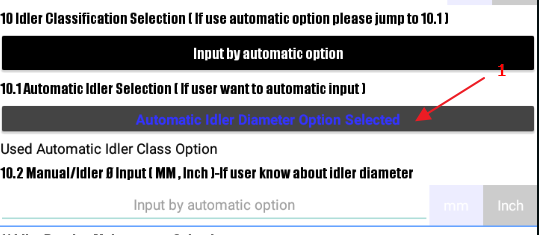
Step 18. Input the idler class or idler diameter if user know the idler diameter ( Option 1 = (10.), Option 2 = (10.1) , Option 3 = Manual idler diameter input (10.2)) For this example use automatic idler option (10.1)
Step 19. Input idler bearing maintenance factor


Step 20. Input Drive and Tail pulley and select unit

Step 21. Select drive pulley diamond lagged 10 mm and tail pulley ( bare pulley ), After select users can see "4" and "1" in (14.)

Step 22. Select Wrap angle (180)


Step 23. Input quantities of the pulley on the tight side and slack side or other quantities pulley.


Step 24.Input depth and length of the skirtboard. ( Depth 3 Inch , 1500 mm Length )


Step 25. Select Skirtboard friction factor ( Gypsum 0.5" screening )
Step 26. Input the quantities of the cleaning device ( 1 Primary, 1 Full v-plow ) and click "OK"

Step 27. Input the height of the falling material into the belt conveyor. ( For this example use 3ft )

Step 28. Select load type ( Uniform load )

Step 29. Select the type of drive ( For this example use, Single reduction speed reducer and over 10 Hour/Day )

Step 30. Set the environment condition in (20.)

Step 31. Input the special characteristics

Step 32.Input the Sag limit and belt safety factor ( For this example, use 2% sag and 10x multiplier factor of safety )

Step 33.Input trough type of the conveyor ( For this example, use full trough )


Step 34. Select Belt type and then click "CALCULATE"

After calculate users can see "Guidance for minimum belt selection is (PIW, EP).

Step 35. Click "Check results "to check the full result.


User can save the answer (Anwer file will be saved into the SD Card ) and share the answer to anyway connection on your social application e.g. line, facebook, email, etc.
Thank you.
Anuwat Kongpan
Mechanical Engineer.


Great piece of information
ตอบลบrubber belting conveyor