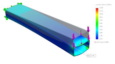
Hello, today I have some free time so I have to write a blog on this topic. The matter of the story is that some people do not accept the results of FEA by beam mesh. So I have a doubt that it's actually a solid mesh in a three-dimensional beam shape. How accurate will it be? Today we will prove it.
First of all, thanks to the trial version of Midas, for which I have compared the MeshFree software too.
There are two types of specimens that we will be testing. It is a full line beam, 1 meter long, and a beam with a slit to insert the beam crosswise. which can be seen in Figure 1.
A simple test is that we lock one end of the beam and apply a force of 500 N on the other end.
The type of the main beam is a JIS G3466 Rectangular tube 200 x 100 x 6. and across the inserted beam is a Square tube 50 x 50 x 6
The section properties of Rectangular Tube 200 x 100 x 6 as below.
Unit mass = 26.4 kg/m
Area = 33.63 cm²
Second moment of area; Ix = 1700 cm ⁴ , Iy = 577 cm ⁴
Radius of gyration; ix = 7.12 cm , iy = 4.14 cm
Elastic section modulus; Zx = 170 cm³ , Zy = 115 cm³
Plastic section modulus; Zpx = 213 cm³ , Zpy = 132 cm³
Torsional inertia = 1,420 cm ⁴
Torsional modulus constant = 200 cm³
and the section properties of Square Tube 50 x 50 x 6 as below.
Unit mass = 7.56 kg/m
Area = 9.633 cm²
Second moment of area; Ix = 29.5 cm ⁴ , Iy = 29.5 cm ⁴
Radius of gyration; ix = 1.75 cm , iy = 1.75 cm
Elastic section modulus; Zx = 11.8 cm³ , Zy = 11.8 cm³
Plastic section modulus; Zpx = 15.3 cm³ , Zpy = 15.3 cm³
Torsional inertia = 53.2 cm ⁴
Torsional modulus constant = 18.2 cm³
CASE 1.
SolidWorks 2021 Model and analysis with solid mesh result.
From manual calculation ( Maximum deflection )
Maximum deflection = Pl³/3EI
= (500 (1000³))/(3 x 200000 x 5770000)
= 0.1444 mm
CASE 2.
SolidWorks 2021 Model and analysis with solid mesh result.
SolidWorks 2021 Model and analysis with beam mesh result.
Analysis with MeshFree result. Case 2.
Fig.14 Displacement result from MeshFree analysis. (0.1785 mm)
Result Table.
Case 1. Single beam Stress (MPa) Displacement (mm)
SolidWorks 2021 Solid mesh 12.569 0.177
SolidWorks 2021 Beam mesh 4.33 0.153
Midas MeshFree 15.871 0.177
Manual calculation NA 0.1444
Case 2. Modified beam Stress (MPa) Displacement (mm)
SolidWorks 2021 Solid mesh 10.75 0.174
SolidWorks 2021 Beam mesh 4.33 0.153
Midas MeshFree 16.215 0.185
Manual calculation NA NA
Conclusion.
The stress produced by solid meshing is approximately 2-3 times higher than the stress produced by beam meshing. The FreeMesh effect has the same effect as the solid mesh effect, which is higher. This is caused by a bug called Singularity, which changes the overall reading of the results. Some people may be frightened by this high value or maybe planning the wrong solution.
Displacement values from beam mesh are similar to beam theoretical calculations.
The singularity problem can be eradicated by beam mesh modeling, provided that the beam constraint is known, there must be no cross-sectional change over the entire length. And if there is a change in cross-section, a beam simulation technique must also be used, where it must be divided into smaller beams that meet the definition of a beam mesh.
The MeshFree method does not require mesh generation and does not require to simplify the model before testing, which is very interesting. Also, the results are easy to read, with % of the area of the colored bands to indicate groups. Although the results are shown with Singularity included, with the smart GUI it is known that the Singularity values are small compared to the important values to consider.
EngineerM ConveyorMan.
09-Apr-2022


ไม่มีความคิดเห็น:
แสดงความคิดเห็น
Welcome.